What's New in CONNECT Edition V9.5
This document describes new or enhanced features of STAAD Foundation Advanced since the CONNECT Edition V9 Update 4 (Release 9.4.0.20).
Mat Foundations per AS3600 2018 in the General Mode
The salient features of this module are:
- You can import a
superstructure model from STAAD.Pro. This brings in the support reactions and
column/pedestal data from that model into SFA
or
You can start with a empty model in SFA, define the locations of column supports (if any) and assign the column sizes and loads acting on the foundation through those columns.
- Create a mat foundation job and chooses the code as Australian (AS3600-2018). Select the load combinations (categorized into Service and Ultimate) for which the mat should be analyzed and designed.
- You then specify any additional loads on the mat, if any (e.g., point loads, area loads, etc.) Generate load combinations, if needed. (Load combinations from the STAAD.Pro model can also be imported thru Step 1)
- Define the mat boundary and mesh it to produce a finite element model of the mat. Specify the mat thickness to be used for analysis as well as for design.
- Specify soil supports and/or pile spring supports.
- Perform the FE analysis of the mat.
- Create a moment envelope which is a set of discrete points where the concrete design of the mat will be performed.
- Perform the flexure and
punching shear checks.
The program will recommend a bar arrangement for flexure for the longitudinal and transverse directions for the top and bottom surfaces. In the event of insufficient thickness as a singly-reinforced section, a failure will be shown.
- Perform moment capacity checks for a desired bar diameter and spacing.
Output from the program consists of:
- Summary of minimum/maximum nodal displacements from the FE model
- Summary of minimum/maximum plate element stresses and moments from the FE model
- Summary of maximum soil pressures from the various service load cases/combinations.
- Contact Area report for each service load case/combination. A loss of contact will be evident through a value that is less than 100%
- Report of Sliding and overturning check for each service load case/combination.
- Static equilibrium mismatch report in the event of instabilities that cause overturning or sliding.
- Pile reaction summary for service and ultimate load cases/combinations.
- Details of the flexure design checks for the longitudinal and transverse directions for top and bottom surfaces.
Details of the implementation are described in the Technical Reference manual.
Pedestal Design per AS3600 2018 Code
For mat foundations, pedestals specified beneath the columns can now be designed to the Australian code. They are designed to the rules governing the design of short columns. Design is performed for:
- Axial compression + biaxial bending
- Axial tension + biaxial bending
- Shear force acting along the 2 global directions
The procedure is identical to the one implemented for pedestals located on isolated or combined footings. In the Global Settings menu, you have the option to specify the bottom of pedestal to coincide with the top of the mat or with the bottom of the mat. This will be used to determine the height of the pedestal, which in turn will determine the moments at the bottom of the pedestal due to shears acting from the column.
Output consists of the bar details for longitudinal reinforcement, a table of P-M values for that reinforcement, and the link bar size and spacing for shear, along with the critical load case numbers.
Enhancements to Punching Shear Checks
For pilecaps and mat foundations, for the ACI 318 code (2005, 2011 and 2014 editions), the check for two-way shear due to the column punching through the mat has been enhanced to take into consideration the additional stress induced by unbalanced moments transferred to the mat by the columns. This check is done in accordance with the rules explained in section ACI-318-11 clause No. 11.11.7.2 / ACI-318-14 clause No. 8.4.4.
A similar enhancement has been made for mat foundations designed to the Indian code. The rules explained in sections 30.6.2.2 and 31.6.2.2 of the code have been implemented. The calculation of the "J" term (polar moment of inertia of the punching perimeter) is done using the guidelines of Table E-8 of SP-24 - Explanatory handbook on IS456-1978.
Reinstatement of Bar Spacing Limits for Pedestal Design
The facility for specifying the minimum and maximum spacing between the longitudinal bars of a pedestal has been re-instated for the foundation modules in the General mode of STAAD Foundation Advanced.
Miscellaneous enhancements
- A facility is now available for specifying the modulus of elasticity of concrete for the analysis of mat foundations. This value will then be passed on by STAAD Foundation Advanced to the finite element model of the mat for analysis in the STAAD.Pro analysis engine.
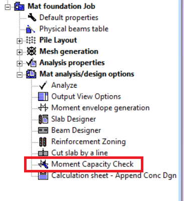
- For mat foundations, there
is a facility called Moment Capacity check where the program reports the
flexural capacity of the slab for a user-specified value of bar arrangement.
For all the codes available in STAAD Foundation Advanced, like ACI, Indian, Euro, etc., this has been enhanced to identify and report a failure in the event of over-reinforced conditions, as well as when the arrangement is so dense as to violate spacing limits mandated by the codes.
- The algorithm for finding the optimum size of isolated footings has been improved so that if the size limit is reached for one of the plan directions, the program will continue to increment in the orthogonal plan direction if there is room for doing so until that limit too is reached.
- Improvements have been made in the tests done to determine if a column included in a mat foundation job should be excluded from consideration for that job or not, due to a mismatch in elevations between the mat and the bottom of the column. The reporting of such instances too has been improved to include the column number of such columns. This will also eliminate the false warnings which appeared in version 9.4.0.20 of STAAD Foundation Advanced.
- More checks have been incorporated in the program to identify input data errors. An example of this is: If the gravity load cases (dead and live) are assigned negative load factors, a warning message will be displayed in the output pane to notify the user of this condition, along with the number of the primary load case / load combination case. Another one involves identifying and warning when column reaction loads are present where no column has been associated with that load.
- Starting with this release, for mats supported by a combination of piles and soil, the compression-only attribute will not be applied to those support springs which represent the locations where piles are present. This is because, piles are treated as being effective in compression and tension, due to which, those points cannot lose contact with the mat. In earlier versions of STAAD Foundation Advanced, those supports were treated as compression-only, leading to loss of contact if there was sufficient uplift-causing forces and/or moments acting on the mat from the columns.
- For isolated footings designed using the Set Dimension method, if the footing size is so small as to cause the eccentricity of loading M/P to be large enough to fall outside the footing, no messages indicating the cause of the design failure were reported in past versions. This condition is now being identified and reported with a clear message.
- For this version, for tank foundations, the value of the parameter termed Av is set to 0.372. Av is defined in the API 650 code as the "Vertical seismic acceleration parameter" or "vertical earthquake acceleration coefficient" and is used to calculate the pressure on the soil due to the vertical force resulting from the sloshing effect of the liquid contained in the tank for load combinations containing seismic cases. As per API 650 Clause E.6.1.3 bullet point 2, the maximum value of Av is 0.14×SDS. The value of 0.372 is based on the maximum value of SDS which as per the ASCE 7-05 code is (2/3)×3.9844 for the ZIP code 93016 for the town of Filmore, California. In the next version, there will be facility available in the Input screens of the Tank Foundation module through which users will be able to directly enter Av or SDS
- For some of the PLANT foundation modules, the shear forces and bending moments used in the concrete design of the footing for each load case are now reported in the output pane. This should assist users who wish to verify the correctness of the values deemed to be critical for each of those checks.
- For combined footings, one of the important details that was omitted earlier such as the critical load case responsible for the final footing size is now reported.

Defects Rectified
- For isolated footings designed to the Eurocode, an error in the value reported for area of steel provided for flexure has been corrected.
- Miscellaneous errors in the flexure design of mat foundations per the Indian code (IS456) have been corrected.
- An error in the reporting of the location of critical shear and moment for isolated footings has been corrected. The location is reported in terms of the distance from the top left corner of the footing in the global axis system.
- For a vertical vessel on square footing, there was an error in the reporting of the value of punching shear perimeter when the pedestal has an octagonal shape. This has been corrected.
- For combined footings, when the columns are positioned with respect to the footing in such a manner that the profile of the punching shear boundary is a part rectangular shape, the perimeter value was incorrectly reported. This has now been corrected.
- For mat foundations designed to the ACI 318 code (2005, 2011 and 2014 editions), various errors reported by users and those found in our internal tests in the design of pedestals have been corrected.
- In past versions of STAAD Foundation Advanced, for mat foundations, the effective depth reported in the calc sheet for flexure design was based on the size of the minimum bar required, and not on the basis of the bar finally selected. This has been rectified.
- A mismatch between the moment capacity value reported in the program's GUI and the value reported in the calc sheet has been corrected.
- Some errors in the headings that appear in the punching shear report table for mat foundations have been corrected.
- For isolated footings, the program was failing to take into consideration the size limits (minimum and maximum bar sizes) specified by the user for top reinforcement. This has been corrected.
- Some instances were found where the program crashed when displaying the calculation sheet for mat foundation models. These have been corrected.
- For isolated footings, it was found that in some cases, the bars reported for flexure were larger than deemed necessary. In other words, a smaller diameter bar would have sufficed. This has been corrected.
- The check built into STAAD Foundation Advanced to identify whether the user has failed to assign supports - soil or pile - to the mat foundation model, and prevent the analysis from being launched if that condition is found to be true, was failing in some cases. This has now been corrected.
- In builds 9.4.0.20 and older, the footing size calculated by the program under the combination of buoyancy and uplift load from column was larger than necessary due to a defect that caused the buoyancy effect to be counted twice. This has been corrected.
- In builds 9.4.0.20 and older, for pilecaps of a 2-pile arrangement, flexure design for steel spanning the transverse direction of the pilecap was not reported. This has been corrected.
- In older versions of STAAD Foundation Advanced, an incorrect value of effective depth used be reported for the punching shear check for corner piles for pilecaps in the general mode, and has been corrected.
- In certain models of vertical vessel on square footing, if the minimum bar dia. was set to be equal to the maximum bar dia. in the "Design Parameters" page, and that bar size was not sufficient to meet the design requirements, the program would hang. This has been corrected.
- For isolated footing models, in some cases, for one-way shear check, the program was designing the footing to a one-way shear force based only on the side experiencing the highest soil pressures from the bottom. A greater shear force could potentially have been acting on the other side due to the weight of soil and surcharge acting downwards, but this was not designed for. This has been corrected. This also affected footings where the column was eccentrically located resulting in the one-way shear line on the soil pressure side falling outside the footing.
- For horizontal and vertical vessels supported on an footings on piles, if the force in any of the piles exceeded their capacity, it wasn't reported as an error or warning in the calculation sheet. This has now been rectified, and along with the pile reactions reported under the table titled "Maximum Pile Reactions for service load cases", an error message will be displayed in the output pane.
- During pedestal design, an error in the calculation of number of dowels and dowel circle diameter for a vertical vessel on a square footing has been corrected.
- A defect that prevented the calculation sheet from being displayed for pilecaps in the General mode of STAAD Foundation Advanced has been corrected.
- In the pilecap module of the general mode. if the thickness specified by the user for the pilecap is found to be insufficient, the program indicates this through a message in the calculation sheet. However, this did not trigger any error message in the output pane. This has now been corrected.
- For the tank foundation module, there was an error in the computation of the load resulting from the pressure due to live load on the roof of the tank.
- For the tank foundation module, there were some errors in the calculation of factor of safety in overturning at the top of the ringwall. Consequently, the load case number reported as critical for this condition too was not identified correctly in some cases.
- For Tank foundations, in the Internal Soil Bearing Check, the pressure on the soil at the level just below the granular fill is reported. However, this value did not include the contribution from the concrete slab component named as PCC, for the non-seismic as well as the seismic load cases. This has now been corrected.
- For mat foundations, an error caused the Moment Capacity values for a user-specified bar arrangement to be incorrectly calculated. This has been corrected.